Rendering Outlines with a Post-processing Shader
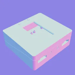
Outlines are key to discerning details in 3D CAD models. Let’s compare the modeling view from Fusion 360 with a render from model-viewer:
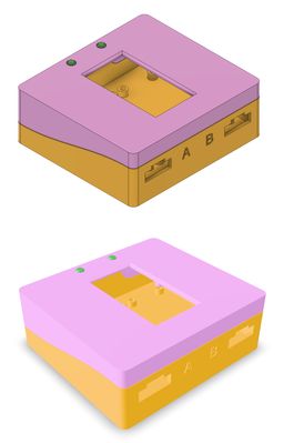
Comparison of CAD modeling view (top) from Fusion 360 and a rendered view (bottom) from model-viewer
The same model looks different, even ignoring the slight camera position difference due to manual positioning. The lighting and shadows are different, the materials look different, and the colors are different. The perspective is different. Even if I adjusted the lighting, added textures, and used realistic material settings, I’d prefer looking at details in the CAD view because of the outlines. I've written about this elsewhere in this series, including Experimenting with CAD models in model-viewer.
Could I add outlines? Maybe! I didn’t know anything about how model-viewer worked. I browsed the documentation around extensions and modifications, then set the project aside to leave an opening for inspiration.
§ Inspired by Mœbius
A few weeks later, I ran into an in-depth article about creating a post-processing effect inspired by the French artist Mœbius.
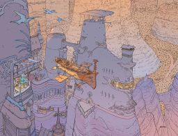
Plate 2 of Voyage d’Hermès, by Mœbius. Image from Sci-Fi-O-Rama.
This article builds a shader, step-by-step, to add outlines, adjust shadows, and create a hand-drawn appearance to a rendered scene.
To extend model-viewer, you can build on its foundation, three.js, or use model-viewer-effects, which adds post-processing effects. The article used react-three-fiber, a library that connects React to three.js! I couldn’t copy-and-paste the code samples—I couldn’t find an example for model-viewer-effects using a custom shader—but this was exactly the inspiration I needed.
§ Adding a custom shader to model-viewer
I couldn’t find a demo with a custom shader and model-viewer, so I needed to create one. Per the documentation, I set up postprocessing and model-viewer-effects. model-viewer-effect’s documentation on custom effects aims folks at the Postprocessing Custom Effects wiki page. After reading and re-reading the Custom Effects wiki page, I had a small understanding of how it works.
A scene is rendered and given to the custom effects. The effect runs C-like code for each pixel of the source image, outputting a pixel used for the output image.
With much effort, I had the skeleton of a custom effect rigged up to model-viewer. I was able to use it to add a partial outline to the model. This was a promising start, but I couldn’t make any improvements. I needed a deeper understanding.
§ Background
-
WebGL is a JavaScript API that uses OpenGL ES for high-performance 2D and 3D graphics rendering in the browser.
-
Three.js (GitHub) is a JavaScript library that usually uses WebGL for rendering.
-
model-viewer (GitHub) is a JavaScript library and Web Component that uses three.js to display 3D models in the browser.
-
The Poimandres postprocessing library adds post-processing effects to three.js.
-
model-viewer-effects (GitHub) is a library and Web Component that uses the postprocessing library to add effects to model-viewer.
§ What is post-processing?
Post-processing involves rendering a scene to an intermediate buffer before applying effects. Some effects can be applied directly to the intermediate render. Other effects are more complex, needing multiple passes or additional information.
§ What is a shader?
OpenGL renders images using a rendering pipeline. The Khronos Group will remind you that an OpenGL implementation renders images, while OpenGL is only a specification and an API definition for rendering. Some pipeline steps run programs called shaders. There are different types of shaders, like vertex shaders, which run for each vertex of the geometry, and fragment shaders, which run for each fragment, which is almost the same as a pixel. Shaders vary, but the prototypical vertex shader transforms a vertex’s 3D coordinates to a 2D screen position, and the prototypical fragment shader sets the color of a pixel. OpenGL shaders are typically written in OpenGL Shading Language (GLSL), similar to C.
§ Creating the outline effect
There are many ways to make outlines in 3D graphics. See 5 ways to draw an outline and Generating Beautiful 3D Outlines, for instance. One method uses a fragment shader. Pixel-by-pixel, it looks for edges and draws outlines on the detected edges. It uses different versions of the scene to detect more edges.
Based on advice from some of the articles I had found, I started with a grayscale version of the rendered scene.
The grayscale version of the rendered scene's colors
I use the Sobel operator to detect edges. For each point in the image, the Sobel operator looks at the eight neighboring points to determine if the center point is an edge. Many image operations can be done by looking at a small window of pixels around each pixel. Each output pixel is created through some math done on that small window of input pixels. This is called convolution. It can be tricky to understand. The Mœbius shader article has an interactive Sobel demo, and I found a similar interactive sharpening demo. If you know of something better, please let me know! The Sobel operator isn’t perfect, but it’s easy to implement in a fragment shader. If the Sobel operator’s calculated value is higher than some threshold, I count it as an edge and color the pixel black.

Edges detected from the grayscale version of the rendered scene's colors
It does an okay job—better than I was expecting! Much of the interior geometry is lost, but the silhouette and some details are outlined.
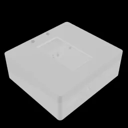
The next aspect used to add edges is depth. The depth map is a grayscale image where the color represents the distance from the viewpoint to the object.
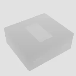
The depth map, where the pixel brightness represents how far away the point is from the viewpoint
Once again, the Sobel operator detects edges.

Edges detected from the depth map
Using the Sobel operator to detect edges using the depth map reveals edges around the window, the cutouts, and the silhouette. Most other edges are missed.
The next aspect used to detect edges is the normal map. The normal of a surface is the direction the surface faces, and a normal map is an image that colors each surface based on the direction the surface faces.
The normal map, where colors represent the direction the surface faces
Using the Sobel operator, again, we highlight detected edges in the normal map.

Edges detected from the normal map
Wow! For this model, at least, the detected edges create a detailed outline. Parallel surfaces without intermediate geometry seem to be the cause of most missing edges. There is at least one clever improvement to this method documented in the resources. For example, when looking at the top from an angle, the far edges of the buttons usually aren’t outlined.
Next, I combine all the detected edges.

Edges detected from the grayscale version of the scene's colors, the normal map, or the depth map
This looks pretty good!
Let’s overlay the edges on the rendered scene.
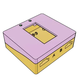
Detected edges overlaid upon the original rendered scene
Looking critically, the A and B labels are missing outlines from most viewpoints. Other edges are missing, and there are often so many outlines drawn on the standoffs that it looks like shading. There’s an issue with aliasing.
It isn’t perfect, but this looks even better than I had hoped!
§ Demos
While working on this article, I made a tool to take screenshots of the shader in various configurations. I kajiggered it into an interactive demo where you can play with the shader settings. As I was brainstorming ways to present an explanation, I made another demo that shows all the views of the model in synchrony.
§ Next Steps
§ Shader Improvements
Assuming this works as well on other models, it’s good enough for me to consider outlines handled. In case I change my mind (or for the inevitable tinkering), I’ve collected some articles that detail improvements and alternate approaches.
I haven’t yet reviewed the shader with care. I built this shader through experimentation and chose the various settings haphazardly. I’m certain there are real improvements to be made and bugs to fix, even before improving the actual algorithm.
§ Moving on
The next step is to wrap this outline effect into a Web Component that integrates with model-viewer-effects. No one should have to write JavaScript to add this effect. It’ll go inside <model-viewer> tags like the built-in effects.
Additionally, I want to create a one-page “quick and dirty” example for using a custom shader with model-viewer, and an example model-viewer-effect-alike Web Component. I don’t think custom shaders for model-viewer are commonly asked about, but I want to help document them.
§ Resources
- WebGL: 2D and 3D graphics for the web Mozilla’s WebGL documentation. It includes reference material, tutorials, guides, articles, and talks. It seems to be a good starting point, and what I’ve read has been clear and helpful.
- Khronos OpenGL wiki Khronos, the group behind OpenGL, has an in-depth wiki.
- 5 ways to draw an outline Overview of five ways to draw outlines in 3D graphics.
- Generating Beautiful 3D Outlines Three ways to draw outlines: offset and scale, stencil and wireframe, and post-processing.
- Moebius-style post-processing and other stylized shaders Quite good. Dissects “Mœbius style”, which includes outlines. Uses post-processing with depth and normals. Code is JavaScript, using react-three-fiber, but definitely doesn’t require React knowledge to understand.
- Sketchy Pencil Effect with Three.js Post-Processing Uses post-processing with normals and grayscale version of the rendered scene. Code is JavaScript, using three.js.
- Edge Detection Outlines
- How to render outlines in WebGL
- Outlines via Postprocessing
Post-processing, uses depth and normals. Code is C# for Unity. - Unity Outline Shader A detailed walkthrough creating and improving an outline shader in Unity. Code is C#. It seems to be similar but significantly improved from what I’m doing here.
- Better outline rendering using surface IDs with WebGL (GitHub) Highlights issues with using normals, and assigns surface IDs instead.
- Pixel-Perfect Outline Shaders for Unity Different method than our post-processing edge-detection, but good article. Uses a vertex shader to add a slightly larger mesh. Code is for Unity.
- Moebius-style 3D Rendering ~8-minute video. Breaks down the “Mœbius style”, and imitates it in Unity. Helpful explanation and visuals. Beginner-friendly, but it expects 3D rendering knowledge.
If this was helpful or enjoyable, please share it! To get new posts, subscribe to the newsletter or the RSS/Atom feed. If you have comments, questions, or feedback, please email me.